Quick Facts
- Topics
- Electrification
Read the complete HVRF Expert FAQ
Next, dive deeper into the frequently asked questions we’ve received from engineers in the field and corresponding responses from Trane® / Mitsubishi Electric product experts.
A: HVRF allows for the same simultaneous heating and cooling to each individual zone providing the same heat recovery as standard VRF. HVRF has active chilled water and hot water temperature reset providing even more comfortable, milder off-coil temps to the indoor space while still providing similar efficiency. HVRF can reduce the defrost time by up to 50% over traditional VRF with the use of heat recovery defrost against the built-up circulating hot water, which also adds to space comfort.
A: Due to the additional heat exchangers and inverter pumps providing chilled and hot water to the indoor units, an HVRF system’s seasonal efficiency is approximately 10% less than standard VRF.
A: The HVRF main HBC has similar or lower sound power levels than a comparable VRF Branch Controller in cooling or heating mode, but with additional components its recommended to be installed in a small mechanical room or closet, if possible. The noise levels of the indoor units in the occupied space are lower than traditional VRF as there’s no control valve in the HVRF indoor units or refrigerant, making it ultra quiet in the occupied space.
A: Due to the added components in the Hybrid Branch Controller, the equipment first cost will be slightly higher than traditional VRF. HVRF makes up for this with easier installation from the Hybrid Branch Controller to the indoor zones, especially when using pre-insulated, multi-layer composite piping. In many small space applications like hotels, multi-family residential, and senior-living refrigerant concentration factors can lead to additional costs for refrigerant concentration limits or refrigerant monitors, and additional rules above and beyond ASHRAE 15 and 34. The overall install cost of HVRF can be similar or less than VRF depending on the application. This will hold especially true for the adoption of A2L refrigerants in North America in 2026, which will increase the need for more safety measures for standard VRF.
A: Chillers are highly efficient, high comfort systems and make commercial sense in a wide array of applications when considering large(r) scale AHU’s and fan coil systems, but can be expensive in smaller scale applications. Additionally, the push towards electrification of heat and heat pump technology over fossil fuels for heating applications create many incentives for the use of VRF or HVRF due to the heat pump’s capability to maintain high coefficient of performance (COP’s) in heating based on an all-electric source. HVRF provides the benefits of a 4-pipe chiller system with the simplicity of design and installation of a traditional VRF system. HVRF is smaller scale, modular, and uses the same tried-and-true built-in control architecture of a standard VRF system with heat recovery to optimize energy efficiency and comfort year-round. Additionally, all hydronic piping and built-in HBC pumps are sized in our Diamond System Builder™ selection software making it easy to design in either plan-and-spec or design-build projects without placing the risk on the designer.
A: At present, we have a similar Medium Static Ducted Indoor unit from 06-48 MBH. Beyond that, we will be adding 2’x2’ and 3’x3’ four way ceiling cassettes and wall mount units in 2024. This will be followed by our high and low static ducted indoor units and a new floor mount console unit. All indoor units have the same look and feel of its comparable VRF counterpart. Apart from being a hydronic coil, each indoor unit will be provided with a built-in manual air bleed valve along with a Trane provided automatic air separator installed at the high point of each indoor unit run out. One of the key differences that you’ll notice on the HVRF indoor units is their milder, off-coil temperatures in the colder seasons and lower sound levels providing more comfort to the end user.
A: HVRF uses the same controls architecture and controllers as standard VRF. All indoor unit controllers are also intermixable between standard VRF and HVRF, there’s no difference in the visuals or user interface on buildings that incorporate both.
A: Standard Copper or Multi-Layer Composite Pipes (MLCP) can be used on the hydronic piping. Multi-Layer Composite Piping is newer to the North American market, but offers the perfect fit for HVRF as it can reduce cost and is also available in longer coils that can reduce the amount of fittings and couplings over copper. We will be providing a Multi-Layer Composite Piping offering due to the limited availability in the US today, but it has been used globally for many years, typically on radiant systems where higher water temps are in play. Our Multi-Layer Composite offering will be a PERT-AL-PERT construction with full flow fittings. This specific piping offers the benefits of being able to handle the thermal stresses of changing from cooling to heating repeatedly with a similar expansion rate to copper and will be pre-insulated to 1” or 1.5” based on pipe size to meet IECC insulation standards for water from 41°F to 140°F in the pipe. In addition, the aluminum layer in the composite offers a permanent oxygen barrier to prohibit air from getting into the closed loop system and prevent long term corrosion of components.
A: Based on our global experience with the product, we are not going to allow standard PEX-a piping on the system for the US market. Traditional PEX-a has a much larger expansion rate than that of copper or MLCP piping by a factor of up to 20:1, which when used makes it very prone to capturing air pockets in the piping. This paired with our smaller inverter driven pumps in the HBC can make it very difficult to purge air out of the system during initial fill. Typically PEX-a piping has a sprayed on oxygen barrier which can be more prone to damage during install and allow air into the system deteriorating equipment life. Thus, we’re providing the MLCP offering as a proven solution for HVRF changes in water temperatures. It offers a visually clean look while reducing the install costs compared to copper. Additionally, it helps to reduce the potential for corrosion or pitting that can occur with copper if not properly maintained, thereby avoiding a potential reduction in system efficiency and longevity.
A: If using copper piping, we recommend using either threaded or press connections on the piping, and do not allow soldered connections due to the potential harm the flux can cause on internal components of the system. We will also allow the water piping to be brazed with a similar nitrogen purge to prevent oxidation inside the pipe like traditional refrigeration methods, but this will likely be less common. If copper is used, additional options will be provided for NPT or press tailpieces on the various required hydronic accessories that go with the system.
A: Our water quality requirements for filling the hydronic loop can be found in the Hybrid Branch Controller Data Book and Service Manuals. It’s recommended that all fill water be pre-treated or be demineralized onsite with an optional disposable demineralizing filter accessory Trane will offer to remove any dissolved solids. The system also allows for the use of Propylene Glycol up to 50% concentration by volume for cold climates and built-in corrosion prohibitor ~25% concentration by volume depending on the specific manufacturer/product.
A: We recommend the system be flushed thoroughly on initial fill to eliminate any leftover installation debris. Then, if using pure water in the system, we recommend the use of approved corrosion inhibitors in the water system as a preventative maintenance measure along with regular testing of inhibitor levels in the system. These can be easily added with the use of the mini-system feeder accessory and expansion tank bracket with a bypass fill valve.
A: Yes, the water temperature can vary from 41°F to 140°F which will cause expansion of the water within the system and thus requires a small expansion tank to protect internal components from the thermal stress. Our Diamond System Builder software will calculate the total water volume for individual weather conditions using copper or MLC piping and calculate the recommended expansion tank volume.
A: Each main hybrid branch controller is provided with a dedicated expansion tank port and dedicated fill line port. There are two main options when designing and incorporating the fill line:
- Permanent Fill Line – We will provide one option for a permanent fill line that includes a potable rated strainer, isolation valve, double check valve w/ drain, and pressure reducing valve with pressure gauge. If local code requires a testable RPZ (Reduced Pressure Zone) style double check valve, one can be provided locally. Typical operation would be after initial fill and air is bled from the system. The isolation valve would be closed to incoming water as it’s a closed loop system and the only make-up that’s needed is to remove any entrained air out of the water through the automatic air separators.
- System Feeder – We’ll provide two sizes of mini system feeders (4.5 gallon and 17 gallon) that are sized using Diamond System Builder, our equipment selection and system layout software. If using a system feeder(s), it would replace the permanent fill line to each Main HBC. The system feeder is a great option to reduce install costs for adding an additional water line to each main HBC and should be paired with the expansion tank bracket for faster initial fill bypass capabilities. Another advantage of the system feeder is in the event of a leak, it has a built-in float alarm in the tank that can be tied into the building management system to catch the issue before any major water damage occurs.
A: The HVRF system will use the same standard outdoor units used in our VRF systems, with additional firmware to support the Hybrid Branch Controller. To start, the system will be compatible with the following outdoor units:
- High Efficiency N-Generation Air Cooled R2 (6-14 Ton) single modules
- Water Cooled L-Generation R2 (6-14 Ton) single modules
A: While the Main Hybrid Branch Controllers may seem very large due to all of the piping coming off of the front of the branch controller, they take up very similar overall installation space/clearances. Due to additional components like the heat exchangers, pumps, and valve blocks they are slightly heavier than a traditional VRF Branch Controller.
- 16-Port Main HBC (TCMBM0108VA11N4)
- 70-7/8” L x 28+9/16” W x 11+3/16” H
- 273.37 LBS
- 8-Port Main HBC (TCMBM1016VA11N4)
- 59-7/8” L x 28+9/16” W x 11+3/16” H
- 240.30 LBS
- 16-Port Sub HBC (TCMBS0108VB11N4)
- 59-7/8” L x 28+9/16” W x 11+3/16” H
- 107.55 LBS
- 8-Port Sub HBC (TCMBS1016VB11N4)
- 59-7/8” L x 28+9/16” W x 11+3/16” H
- 149.91 LBS
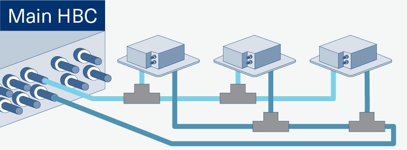
A: You can connect up to three indoor units on a single port off of the HBC, totaling up to 30MBH. When multiple indoor units are connected on the same port, reverse return piping should be used for water balancing.
A: HVRF has the ability to defrost against the built-up hot water temperature in the hydronic loop. This ability to pull heat from the water loop allows for a shorter defrost time, typically a 50% reduction in time depending on system configuration. If the internal water loop were to drop below 83°F, the system will then go into a traditional defrost cycle bypassing the HBC water loop like traditional R2 VRF. In either case, the indoor fans will shut off during defrost to speed up the defrost operation and return to normal operation more quickly.
A: HVRF system is not permitted to connect to third party coils or emmiters at this time, and there is no interface kit available. The system instead will continue to be refined to meet market demand by adding additional indoor unit styles and offerings.
A: The HVRF system offers very similar piping distances and lengths to a traditional VRF system. Below images depict the overall limitations:
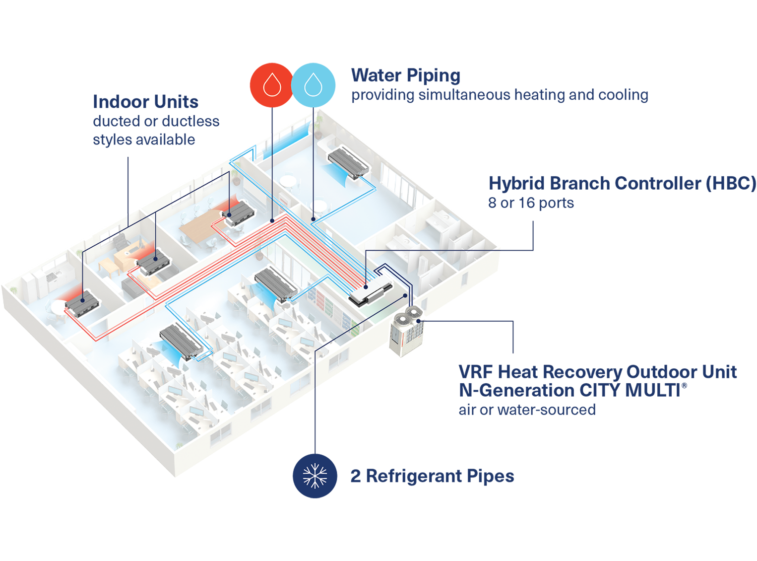
HVRF is a breakthrough technology that incorporates the efficiency and heat recovery benefits of a VRF system with the additional comfort and control of a 4-pipe chiller system by utilizing hydronic indoor units. As new refrigerant regulations and design challenges attributed to ASHRAE® 15 come into effect, HVRF serves as a possible all-electric zoned comfort solution. It can be tailored to fit various applications with specific zoning requirements such as hotels, offices, hospitals, multi-family, schools, dorms and senior living facilities. Each designated indoor unit can be individually controlled by local remote controllers to provide better overall occupant comfort for individual settings.

Trane Engineers Newsletter: Hydronic Variable Refrigerant Flow Systems
In this Engineers Newsletter (EN), Trane spotlights hydronic variable refrigerant flow systems; the next generation of all-electric heat pump systems that can help achieve building decarbonization goals, while satisfying upcoming demands for reduced refrigerant charge.
Read Now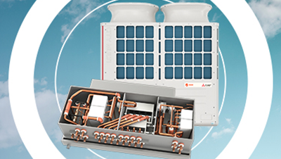
Introducing HVRF: Combining Water and Refrigerant for a Sustainable HVAC Solution
The new Trane® / Mitsubishi Electric HVRF two-pipe heat recovery system uses a combination of water and refrigerant to provide all electric, simultaneous heating and cooling to multi-room buildings such as hotels, dormitories, and multi-family residences.
Watch Now